
Swapping your D14A3 or D14A4 ECU to an OBD1 type
This article describes what I did to go from SFi (Simplified Fuel injection, almost like DPFi (Duel Point Fuel injection)) to MPFi (Multi Point Fuel injection). Specifically this article goes into the details of the ’96-’98 era pre-facelift Civic with chassis code EJ9. There are other chassis which are practically the same. But there are also the MA/MB chassis Civics with D14A7 and D14A8 engines for instance and the OBD2b EJ9 facelift Civics to name a few. Similarly these Civics can very probably be converted to run an OBD1 ECU in a similar fashion, but the details may be (very) different. Please consult my other pages and especially the pinout pages on this website and see if you can work it out. Also if you have information about such conversions I am very happy to share that information here on this website.
The OBD1 conversion can practically only be performed if the IM (intake manifold) is already swapped for a sideflow IM (or do it simultaneously), see my article. This is because the RACV (Rotary Air Control Valve) on the TB (Throttle Body) cannot be controlled by the OBD1 ECU and therefore has to be replaced by an IACV (Idle Air Control Valve) on the IM (a.k.a EACV).
The reasons for doing this swap are easy:
Reason 1: you get 4 separate controlled injectors instead of 2 pairs of injectors, so it may improve overall efficiency of the engine. (On the stock D14A3/A4 engine injectors 1 and 4 are connected together and 2 and 3 are. That is basically what makes it SFi).
Reason 2: nobody I know knows how to reprogram the stock D14 ECU, but the OBD1 ECU’s are very well known. So adjusting the engine management will be easy and you do not have to piggyback it (which in my opinion is the bad way of getting some hp). Reason 3: adding VTEC in the future is easy.
Note: before doing the OBD1 swap you need the IM swap!
Extra note: ok an OBD1 swap can be done without IM swap if you really like to know. I did it once on an EJ6 in 2014, the in-its-time-pretty-famous Jamex Turbo Civic. The IACV was placed on the original TB RACV position using a custom flange I made.

Ok, lets get back on track to OBD1 swapping. There is a hard way and an easy way to do the OBD1 swap, most of this article is about the hard way.
I will try to tell every detail of this swap at the moment. However, I might have missed something. So far I know I am the first to have done this swap (and had a good result). Since I was the first to do this correctly, I had not all information there is today. In retrospect, I did it the though way. But at least I understood the complete wire loom of my car’s engine. For everybody having an interest in the EJ9 and how I converted it to OBD1, read the entire article. But when you have low skills on wiring and you are in a hurry, scroll way down for the incredible easy and not so expensive method to do it OEM style plug and play.
Parts required:
– Distributor of a D15B7 engine (TD-41U).
– IACV a.k.a. EACV from an OBD1 engine if you did not have it on your IM already.
– P06 ECU preferably (with stock 190cc injectors chipping is required).
– Custom conversion harness (see instructions) or at least a set of OBD1 ECU connectors to repin.
– Make sure you have extra wires and connectors for the distributor and IACV.
Optional:
-240cc injectors to replace the 190cc stock injectors, 240cc injectors might run well with stock P06 ECU but better have it chipped and tuned right.
– Throttle body without RACV. Not really sure which ones are the best fit, but they do exist.
Notes:
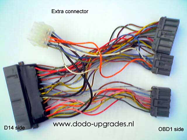
This article is based on the conversion harness I made. It has an extra 10 wire connector for the 2 extra injector wires, 3 extra heated lambda wires and 5 extra distributor wires. Yes 5 that is, so you need actually to run 10 extra wires through the firewall? No, 2 are already there, the injectors. And the heated lambda is not strictly necessary. You can keep the stock lambda but the ECU must be reprogrammed for it or it will throw a code 42 and it will run in safe mode. AND that SUCKS! I can tell from experience.
Conversion harnass:
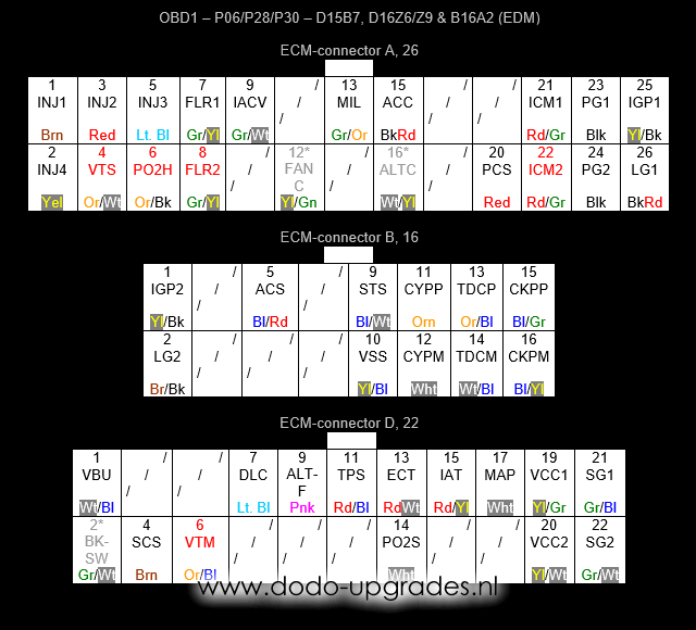
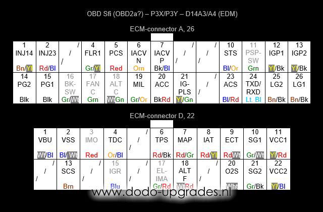
Below the ECU pinouts of a standard OBD1 sheme is shown and the pinout of the D14A3 and D14A4 engines are shown, P3X and P3Y respectively. The OBD1 and P3X/P3Y pinouts vary between engine and year of build in colors or functionality, but the vital information is there. For the record, there are more cars over the world which incorporate the P3X/P3Y type ECU, so for those people the pinout may work as well.
For a more comprehensive list of all OBD1 pinouts that are possible (including IAB for B18C4 engines) please refer to my other pinout pages for OBD1 and SFi.
The A and D connectors for both type of ECU’s are the same. However, the way the pins are numbered is different! I think it has to do with the transition from OBD1 to OBD2a. Furthermore, the fact that the connectors are the same also suggests that all pins can be relocated between connectors A and D to the OBD1 positions and the B connector from OBD1 can be added to the system to make a complete OBD1 conversion. Indeed this can be done instead of fabricating a conversion harnass. First I started with the harnass so errors could be traced and reversing the process was quite easy when it would be a total failure. After a few months of driving succesfully with the harnass I wanted to clean things up a little and instead of using a harnass I relocated all the original pins (sometimes pin sizes differ and a bit cutting and soldering is needed, you’ll find out yourself).
Nomenclature OBD1:
ACC – A/C clutch relay
ACS – A/C switch
ALTC – Alternator relay, not always present
ALTF – Alternator switch
BKSW – Brake switch, not always present
CKP – Crankshaft position, Pulse or Mass, gives multiple pulses during each cam shaft rotation (20+ pulses)
CYP – Cylinder position, Pulse or Mass, gives 1 pulse during each cam shaft rotation
DLC – Data link connector
ECT – Engine coolant temperature
FANC – Radiator fan relay, not always present
FLR – Fuel relay, 1 is usually present, 2 is joint with 1 if present
IACV – Idle air control valve, controls 2 wire type valve
IAT – Intake air temperature
ICM – Ignition firing pulses, 1 and 2 are joined if both are present
IGP – Battery feed, active when key is turned, 1 and 2 are joined
INJ – Injector, the number refers to the cylinder number used (1 is on the side with the belts)
LG – Grounded shield, for CYP, TDC, CKP and PO2S wires, 1 and 2 are joint
MAP – Manifold absolute pressure
MIL – Motor indication light, provides the blinking light (CEL) signal
PCS – Purge cut-off solenoid
PG – Ground circuits, 1 and 2 are joined and connected to chassis at G101 at the thermostate housing
PO2H (HTCNTL or O2SHTC) – Oxygen sensor heater control, connects to battery to activate the heater
PO2S – Oxygen sensor signal
SCS – Service check connector, short to SG2 to read CEL codes
SG – Sensor circuit ground, 1 is for MAP circuit, 2 for all other sensors
STS – Starter switch
TDC – Top dead centre, Pulse or Mass, gives 4 pulses during each cam shaft rotation
TPS – Throttle position signal
VBU – Back up battery feed, always hot (unless battery is removed)
VCC – 5V sensor feed, 1 is for MAP circuit, 2 for all other sensors
VSS – Vehicle speed sensor
VTM – Oil pressure switch
VTS – VTEC solenoid, only present on VTEC equiped vehicles
Nomenclature D14 (OBD1):
ELIMA (ELD) – Electric load detection, not always present and can be ignored
IACV – Idle air control valve, controls 3 wire type valve, Negative and Positive, for the 2 wire type valve conversion keep IACVP and discard IACVN
IGPLS (ICM) – Ignition pulse, identical to ICM from OBD1
IGR – Ignition pulse return signal, not used in OBD1 for the ECU
IMO – Immo system, not available in OBD1 (!)
INJ – Injector, the numbers refer to the pair of cylinders connected (1 is on the side with the belts)
O2S (PO2S) – Oxygen sensor (lambda sensor) signal, identical to PO2S from OBD1
PSPSW (PSW) – Power steering switch, identical to PSW from OBD1, not always present and can be ignored
TDC – Top dead centre LED sensor instead of coils, gives 4 pulses during each cam shaft rotation, can be used instead of TDCP from OBD1 but misses shielding
TXD/RXD (DLC) – Data link connector, identical to DLC from OBD1
Making the conversion work:
The basic of the conversion is very simple, relocate the wires with identical functionality from the original position to the OBD1 position either using a harnass or by repinning directly. Signals not supported by OBD1 can be removed. For ¾ of the wires this process is straight forward. However there are 4 issues that require more attention. These issues are injectors, heated lambda, ignition and idle air control respectively. Those issues are documented further on.
For the conversion harnass it means that an extra connector (or at least some wires) is needed for the following signals which are not supported by the original D14A3/A4 engine harnass:
1: INJ3
2: INJ4
3: CYPP
4: CYPM
5: TDCM
6: CKPP
7: CKPM
8: PO2H
9: additional IGP2 (split!)
10: additional SG2 (split!)
The splits mentioned above at numbers 9 and 10 are needed for the heated lambda sensor. For information on this sensor, see a few sections below under ‘heated lambda’. Here I set out why and where these splits are needed. In all 6th generation Civics, one or two big splitter plugs resides under the IM. In these splitter plugs, several circuits are split into multiple wires. Circuits IGP2 and SG2 are splitted there, as well as some others. Since the heated lambda sensor has 4 wires of which 2 from splitted circuits, cars equipped with a heated lambda are likely to have an additional IGP2 and SG2 split under the IM, which misses in our EJ9 looms. Therefore, we have to construct our own splits. Personally I prefer splitting near the ECU so you can make sure the correct wire is splitted.
My prototype harness was build from yunkyard parts, I was very lucky to get my hands on a free D14A4 ECU that had been flooded (thnx CRX2). The harnass is now located somewere in France -Thomas, I hope you still enjoy it- and looked like this:
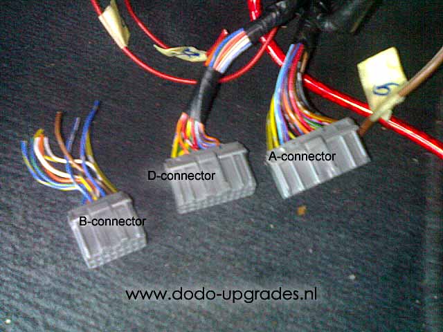
Without the use of a conversion harnass you should work like Leo, here you see his OBD1 conversion re-pinning connectors A and D and adding a ‘new’ B-connector.
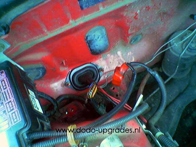
Starting:
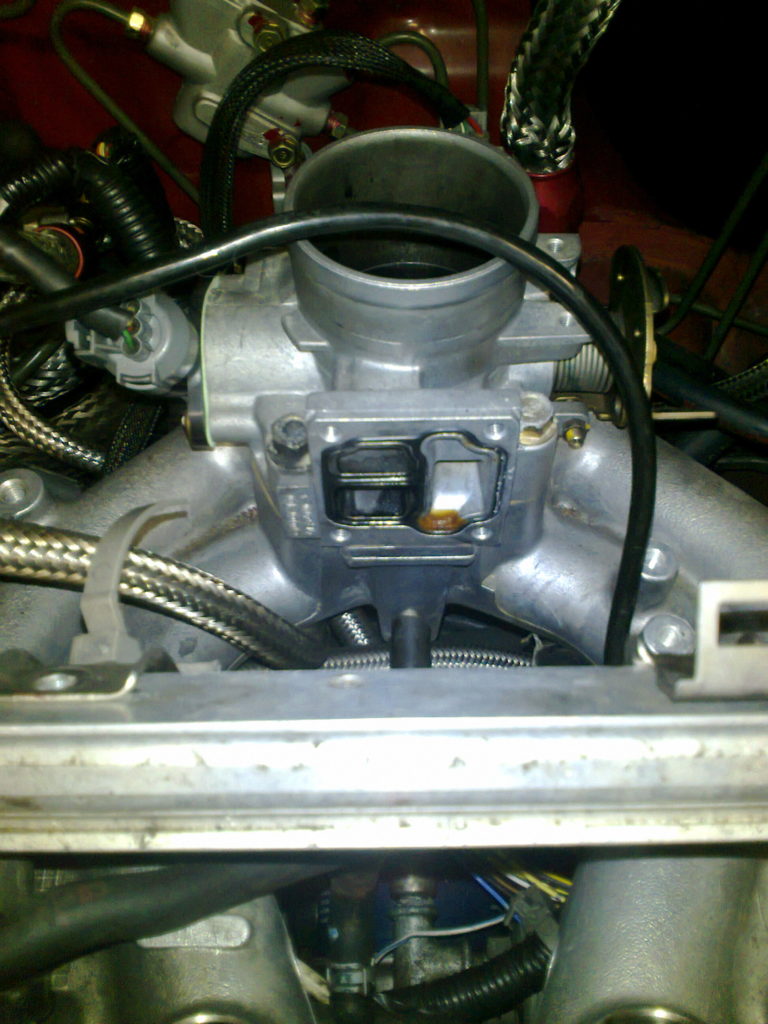
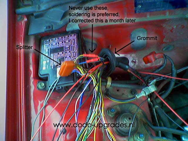
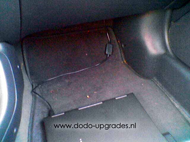
To make work a bit more practical remove the engine wire harness from the fire wall. There have to be 8 extra wires pulled through the grommit shown in the picture. Three of them are for the heated lambda I used and the other 5 are for the ignition. Use different colors if possible, at least mark all the wires. Hopefully looking at this mess don’t get confused. I am just trying to tell were to add the new wires to the engine wire harness under the battery. I did remove the stock grommet and stuffed al extra wires through it without cutting. In a later stadium (not needed for this OBD1 conversion) I even pulled through a Zeitronix lambda wire through there, but cutting the grommit was required this time.
Injectors:
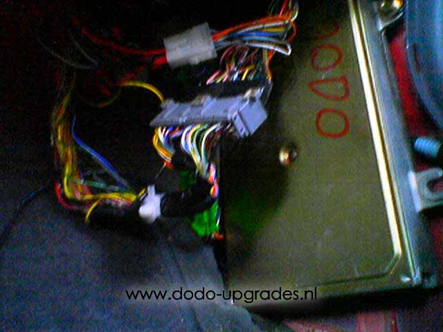
The injector connections are different as follows, the engine has 4 injectors. The stock SFi ECUs have only 2 signal wires going to the injectors so injectors have to be fired in a paired fashion. A ‘normal’ OBD1 ECU has 4 separate signal wires, one for each injector which enables to control each injector individually.
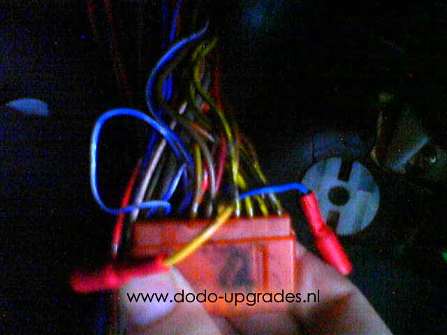
On the stock D14A3 and D14A4 wirelooms the 2 wires from the ECU are spliced in 2 pairs making eventually 4 wires to 4 injectors. This splicing is done in the so-called splicer (or splitter), found above the passengers feet (LHD car at least, RHD I do not know). A very dark picture of my splicer during the process is shown below:
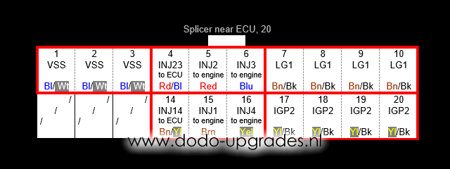
The injector splicer works as follows; sets of 3 or 4 wires are shorted with eachother internally. See the red boxes below indicating which wires are shorted to eachother. For the injectors the splicer splits the INJ14 wire from the ECU into INJ1 and INJ4 wires to injectors 1 and 4. Similar INJ23 is spliced into 2 wires for injectors 2 and 3.
So from the splicer, 4 wires already run to the engine and no additional wire has to be pulled through the firewall for the injectors. When building a conversion harnass, I suggest the following to make it work:
– Connect OBD1 INJ1 (Brown) to the original D14 wire INJ14 which runs to the splicer (Brown/Yellow) on position 14.
– Connect OBD1 INJ2 (Red) to the original D14 wire INJ23 which runs to the splicer (Red/Blue) on position 4.
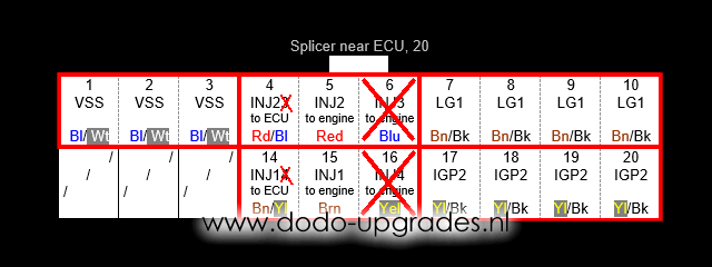
– At the splicer, disconnect INJ3 (Blue) from position 6.
– At the splicer, disconnect INJ4 (Yellow) from position 16.
– Now connect OBD1 INJ3 (extra wire No. 1) to the disconnected INJ3 wire going into the engine bay (Blue).
– Now connect OBD1 INJ4 (extra wire No. 2) to the disconnected INJ4 wire going into the engine bay (Yellow).
This way should give you 4 good running injectors. The wires left on the splitter should be insulated or they could trigger spontaneous fuel injection, unlikely but don’t take risks. Teh splicer schematic is now more like this if everything is done right:
Heated lambda:
The difference between the stock 1-wire and OBD1-type 4-wire lambda is the heater. The heater generally improves accuracy of the lambda and therefore fuel economy in my experience. When at full throttle the lambda sensor is not used, so the maximum performance of the car is not influenced. Most ‘normal’ OBD1 ECU’s require a 4-wire lambda, or they will give error codes. This can be omitted if the ECU is chipped, but I advise to install a 4-wire lambda anyway.
The following 3 wires have be pulled through the firewall:
– PO2H (extra wire No. 8), activator of the heater element
– additional IGP2 (extra wire No. 9), feed of the heater element
– additional SG2 (extra wire No. 10), ground of the lambda sensor
Lambda’s with 1-wire use the exhaust as ground, 4-wire lambda’s feature a separate ground and are therefore also more accurate. The signal cable (PO2S) of the 4-wire lambda is connected to the original signal cable (probably White) of the original 1-wire lambda. So this gives 4 wires total (PO2S, PO2H, IGP2 and SG2) that have to be connected to the 4-wire lambda.
The following common 4-wire lambda sheme’s are known to me:
-OEM lambda; PO2S (White), PO2H (Black), IGP2 (Black) and SG2 (Green)
-Imitation lambda; PO2S (Black), PO2H (White), IGP2 (White) and SG2 (Grey)
-Imitation lambda; PO2S (Blue), PO2H (Black), IGP2 (Black) and SG2 (White)
Make sure to connect the correct wires with each other and you should have a working 4-wire lambda. The PO2H and IGP2 wires from the lambda always have the same colors and it does not matter which order this pair is connected since it is a simple heating element that just needs current to flow through for it to work and heat up..
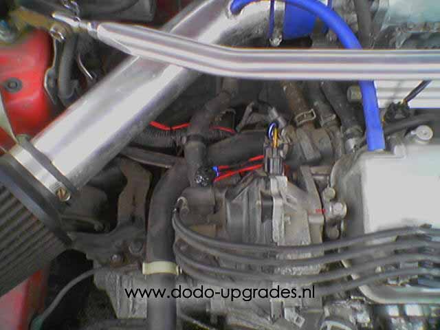
Distributor:
So let’s continue to the distributor. The stock distributor has 7 wires. Only 4 of them can be reused. To get the new distributor with 9 wires running, 5 new wires have to be added. That means 5 wires have to be pulled through the firewall. Those five are already mentioned, I will repeat them here:
– CYPP (extra wire No. 3)
– CYPM (extra wire No. 4)
– TDCM (extra wire No. 5)
– CKPP (extra wire No. 6)
– CKPM (extra wire No. 7)
Honda usually shields all 6 CYP, TDC and CKP wires or the three P variants at least in later models using the LG circuit. I have not used shielding at all but do advice to use it if you can. I expect it just improves the quality of how the engine runs by having a minimum of electro-magnetic interference on the wires. The stock D14A3/A4 distributor is shown in the following picture and diagram.
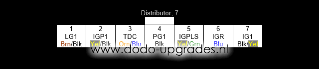
The wires that can be reused are:
– 3 TDC (becomes TDCP)
– 5 IGPLS (becomes ICM)
– 6 IGR
– 7 IG1
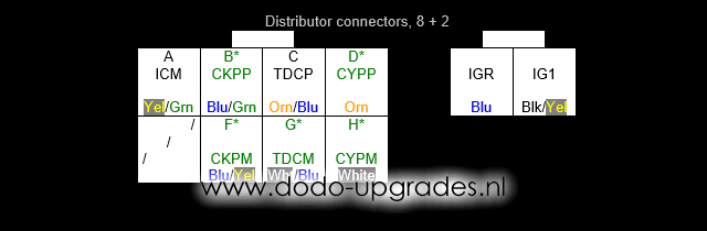
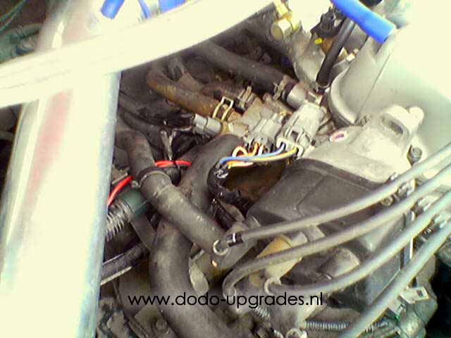
The D15B7 distributor I used is shown in the following picture and diagram. The wires with black fonts can be connected to the old D14A3/A4 wires. The wires with green fonts and an asterix* should be connected to the new wires pulled through the firewall.
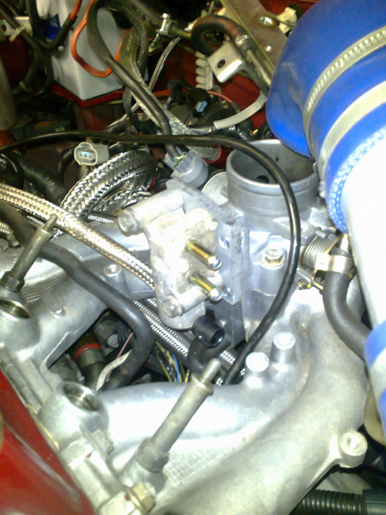
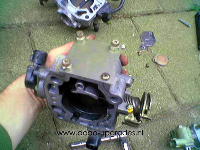
RACV to IACV:
First of all the RACV is useless anymore, so disconnect it. You could use the TB from an OBD1 engine but for me it was pointless. I do not want to have the cold idle valve system at all which is on those. Later I learned that there are OBD2 engines with throttle bodies that would have been a perfect and clean fit without any appendages (I have been told D16Y7 TB but the once I have seen/owned all had the RACV, anybody who knows more is welcome to clarify).
The OBD1 IACV on the manifold will have two wires. You can use the old RACV wires, the connector with 3 wires should be replaced by a connector with 2 wires. You need to throw away one wire of them, I recommend throwing away the orange wire and connect the black/blue wire to the OBD1 IACV signal. The yellow/black wire goes to the yellow/black wire of the IACV. See also my EACV page.

Almost there:
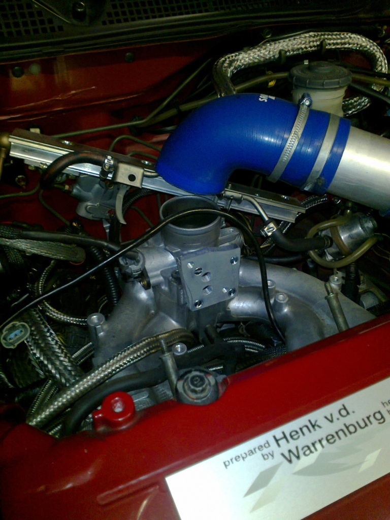
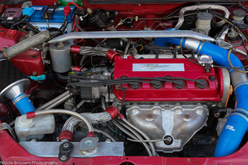
The wiring should be ready by now. Put everything nice in place. Swap the injectors if needed. Connect the ECU and see if the car gets running.
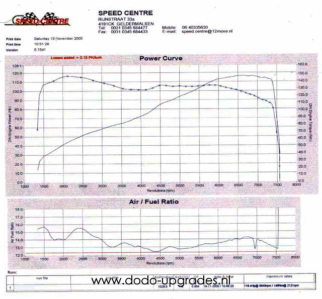
And the result finally came in, 116.4bhp@6648rpm and 142Nm of torque at the bottom… (nice results yes, but later I found out that the timing of the cam was 1 tooth advanced… with an adjustable cam gear and some testing on the dyno it might have scored 120+ bhp I assume, but now I am typing this text the engine already is much more powerful due to the VTEC head I installed quickly after.
Tuning your OBD1 swap:
Getting the best out of your OBD1 swap is done in my experience by the following. Start out with P06 base maps; those originate from the 102 bhp D15B7 engine. You or your tuner should fit the car with a wideband lambda sensor. The fuel maps should all be approximately around AFR 1:12-13 at wide open throttle (WOT). Most Honda engines are not really sensitive to the fuel mixture in that region, and it gets about the max hp. Don’t be surprised if the fuel values end up higher than the stock 1.5 litre maps, you also have more hp to burn them for! This happens since a good upgraded 1.4 engine breaths better than a stock 1.5.
Leave the ignition maps stock. But adjust the ignition timing to 16 deg BTDC, since this is the normal timing of OBD1 engines. The marks on the D14A3/A4 crank pulley are 10, 12 and 14. So you should time the ignition (using a stroboscope) a little bit before the 14 deg mark passes. Only (fine) tune the ignition maps on a dyno please, it’s not worth street tuning ignition maps on the road since only very small changes from stock are needed to get maximum performance in general. And in the case of higher compression ratios and the loud exhausts found on many Civics, it is hard to hear detonation inside the car. It costed me a mini-me once…
The incredible easy and no so expensive method:
Nowadays some very large shortcuts can be made by throwing away the original EJ9 engine loom. Instead search for an EK3 OBD2a engine loom (Civic VTEC-E 96-98). This looms fits on our engine and interior plugs, comes with VTEC equipped and after market conversion harnesses can be bought for it. So the section called ‘conversion harness’ till ‘RACV to IACV’ can all be skipped as far as the electrical wiring goes. As a bonus you could use D15B7 dizzy or even go for the EK3 dizzy. The last will fit straight away, but the first one can be connected with a dizzy conversion harness, readily available these days. That is awfully easy compared to the rest of my write-up.
Just ask anything you need to know and I might help you out or improve this article.
Not all possibilities that come with OBD1 swap teritory are covered in this article. For VTEC on a D14 see D14 VTEC and for wiring VTEC in general see VTEC connectors. IAB (for B18C4 engine), alternator variations and working with A/T versus M/T enginelooms will be added as seperate pages soon. If you have questions on those latters subjects, contact me and I’ll directly let you know or speed up the process to have the pages written.
Dodo Bizar
58 replies on “OBD1 Swap EJ9”
Im about to tackle this project alongside a B-series swap to my EJ9, you are a legend for this write-up, i feel confident doing it thanks to this guide, thanks a bunch!
Great to hear! You’re welcome!
Hi. I’m trying to swap a Supercharg b16 from af eg obd1 I belive into my 97 Civic ej9 obd2a.
Can I just compare the pinout from the original p3x to the pinout on my new p28 Hondata ECU
Hi Casper, yes. Maybe you need additional wiring, but than the stock OBD1 eg also needed this.
Wow, what an amazing guid. I wanted to swap my D14A4-ECU to a chipped one (P06) so i can adjust the maps with crome.
First of all i need to search for some parts and a new ecu but i’m looking forward to do the swap and i’m happy that i found your manual. 🙂
You are very welcome!
What a great guide! A bit mind boggling but I got the general gist! ? but I do have a question, might seem stupid but hey ho
I’ve just got a d16 manifold with a b16 throttle body attached. I want to put it on my 1996 ej9. Question is can I bolt it straight on plug it in and it all works? If not what’s the best way to go about it?
Many thanks
Hey Jack,
Answer is no and yes.
Yes: it works if you go for the OBD1 conversion right away and you get the 2 wire IACV connected and hooked up with your D16 manifold.
No: if you only want the manifold swap to start with keep the original throttle body of the EJ9 for its RACV valve (= the 3 wire IACV).
So would this be a plausible way to make a full d16 swap work? I have a d16y8 with a p28 ecu I’m trying to put in my ej9 and I’m having trouble figuring out what wiring is the easiest to do.
Yes that would work.
So ive been trying for days to get this setup to work. What ive done is take the stock d16 engine harness and body harness, then merged them on the green connector for the d14 setup. Everything appears right, I have fuel to the rail, and spark, but the injectors refuse to pulse. The wires to the injectors are good, and all the grounds appear to be good for the ECU, but it refuses to pulse the grounds… Any ideas?
I suppose the 12V feed to the injectors is working fine? The only reason I can think of (aside from double/tripple check all wiring) that a P28 will not fire the injectors is if it does not get the correct signals from the distributor. So the fault may be in there, although I would guess wiring should have been plug and play with all the OEM harnesses you have used, even without modifying right?
Exactly, its all factory wiring that was untouched, save for the wires that run to the green body harness connector on the stock ej9 setup. Im struggling to find a pinout of that connector as well though, maybe the fault is in that? Swapped three distributors too, none fixed the issue.
Right now Ive just put the ej9 harness back onto the d16, which seems to work okay, aside from some hunting on the idle. You said the stock d16 side mount iacv is closed when not plugged in right?
I added the pinout of the green connector just now because of your question! Its the C131 page. Had it lying around all along. Wanted to check with more chassis specs etc. but I just put the manual EJ9 and automatic Ej6 pinouts I have had in my hands out. Used it for an AT to MT conversion. It was easy but I forgot the details meanwhile.
Yes I believe the IACV is closed when not plugged.
However… you state that you put the EJ9 loom back and it works? You converted the distributor part on that? Or did you run on the EJ9 distributor? The P28 cannot handle that. I am confused in the setup here.
Looks like it wont let me replay again. So I was initially using all EH6 everything. ECU, engine and body harness, but I was getting no injector pulse.
Now Im using ej9 engine/body harness/ecu/distributor and then everything else is the d16 stuff. I basically followed your side flow IM install, so I swapped the RACV TB onto the d16, and swapped on my factory ej9 injectors.
A-ha, EH6 looms, I do not know exactly how those fit in.
What a great read up! I recently took on an ej9 for free and was going stripe and sell it, but after finding this site and reading all your write ups I’m going give the car some new life 🙂
So far I have got a p28 socketed, harness adapter and d16z6 engine what I’m going put in instead (wanted to keep it SOHC instead of going b swap) only problem I have is that I’m struggling to get a loom since the engine didn’t come with one.
I have noticed you say to use a ek3 one which I’m finding hard to source but keep coming up with a mb6 b18c4 loom and wandering if this will work the same?
Thanks for your write ups!
Hey man, unfortunately I am afraid it will not work. If I am remembering this correctly, the MB6 is a loom with all connections to the interior loom inside the engine compartment. The EJ9 and EK3/EK4 looms (at least the LHD cars I work with) all go through the firewall near the ECU and connect to the interior loom there (with the green C101 connector…).
So, i just need to remove the whole ej9 engine loom,replace it with a ek3 one and everything connects right?
And then the conversion harness for the ecu
Yes.
However very recently I found out it has to be specifically the EK3 with D15Z6 engine. There are EK3 chassis with D15B engines that have the same SFI Ecu layout as the EJ9, just a word of warning, but it may be limited to RHD countries only.
I live in portugal and the ek3s here have the d15z6 engine
I will buy a ek3 engine loom and a dizzy then
Thank you for your help
Good day sir, i want to put a d16z6 engine with a p28, in my d14 2000 ej9 and i want to use one of those ebay red jumper harness that converts odb2b to obd1.
As far as i have read ,the only thing that i need to add is a labda heater and vtec wire that i can pin in the adapter , and modify the distribuitor plug pinout
If you have any sugestions or advice it will help very much.
Thank you!
Hey Mihai. I hope it works as you say. I unfortunately have never worked with OBD2b EJ9 chassis somehow nor do I have the wiring schematics for those cars. Could you be so kind and email me pictures of the ECU connectors and the wires? So that I can make out the individual wire colors and position within each connector. If you send me those I’ll double check against the normal OBD2b pinout.
Thank you for the excellent pictures. To anyone else reading this: the OBD2b EJ9 appears to be full normal OBD2b pinout so jumper harnesses work fine. Two heated lambdas. Four separate injectors, no SFi injector stuff to sort out. There is a CKF sensor even, which I am only used to find in D15Z6 engines. Make sure the jumper harness does not connect the CKF wiring to an OBD1 ECU since it generally will make the ECU fail (except when it is a CKF equipped ECU as for D15Z8).
One word of warning, the red jumper harnesses I have had in my hands were made from a very soft plastic which easily gives way and does not hold the terminals properly. If you can spent the money on a harness made from OEM parts it will safe a lot.
Bonjour,
Je suis en train de faire un swap d’une ej9 d14a4 à un D16y8
J’ai un faisceau de ek3 1.5 tout va bien pour mettre sur mon d16, le problème c’est avec mon calculateur un connecteur n’a pas pin donc il ne coïncide pas avec l’écu du d16
Merci?
Sounds like a OBD2a / OBD2b mix may be the cause?
Is the EK3 engine loom OBD2a or OBD2b?
Is the D16 ECU OBD2a, OBD2b or is it an OBD1 version?
With OBD2a parts you should have been fine, but with OBD2b there is one ECU connector not entering the engine wire loom, but directly into the interior loom if I remember correctly.
So I guess your EK3 engine loom may be a OBD2b version and causing trouble, check with the schematics in the pinouts section and you will definetly see which is which.
Hope this helps.
J’ai commandé l’écu p28 ob1 chipté sur cr tune avec un harness obd2b obd1 qui va vers mon nouvelle écu.
J’ai repris les faisceau d’une ek3 ob2b, mais est ce qu’il fait reprendre tout les faisceaux qu’il y’a a l’intérieur du tableau de bord ou il y’a t’il une autre solution ?
Merci de votre aide
Et mon d16y8 et un obd2a mais finalement je vais pas reprendre l’écu d’origine mais une écu chipté obd1
Oh that is unfortunate. I double checked it with some workshop manuals. If I see correctly you miss the A connector for the ECU now. I guess you can manually wire everything together but you really need proper schematics for the C131 connector both for OBD2a and OBD2b (I only have OBD2a) and some spare connector. Easiest by far is getting the harness OBD2a and the engine loom OBD2a as well.
Hey! Super bedankt voor deze guide!
Ik heb een EK3 kabelboom overgenomen voor op mijn EJ9 met d14a4 maar ik heb echt een enorme lading stekkers over.. (6) ik heb 90% gewoon direct kunnen inpluggen maar ik weet niet waar het restant voor is, kan ik dit gewoon los laten hangen? (Met tyraps bundelen uiteraard)
Nogmaals bedankt!
Kevin
Hello , Really Nice topic it opened my knots , but lately i’ve just swapped an d16y4 in my 96 ej9 who has a d14a4 , the d16 work great but i dnt know if im going with 120hp of the engine , or just with 90hp, with a stock ecu p3y , if yes should i go straight to obd1 swap , or i go with a p2k – p76 .. ecu . i also have an TD-80U Distributor and the original harness of the d16y4
In refers im not looking for a big power , its just for fun , for who ever want to play on the road XD
And also a big thanks for this topic ??
Really hard to say. Depends on injector size. Either the amount of fuel will be the same and hence I expect the engine to run lean. Or the injectors are now bigger but the duration is unaltered leading problably to too rich. But I do not really know the Y4, is the VTEC, similar to D16Y8?
Hey
The engine d16y4 , works really great , not too rich , but i dnt think that it will be , because of the old ecu from the d14y4.
D16y4 its an australian , turkish engine , it has 120hp non vtec , is similar to the american d16y7
Hey there, thanks for al your research!
I have a civic from 2000 with a d14a3 engine instead of the d14z1,I have a different IM but how can I see if it’s the d15 one or the d16 one.
I want to change my head for the d16z6 I have one but also again how do I know for sure?
Also is it smart to change the wiring loom complete (interior and engine bay) for the ‘99 model because I want to switch to p06 or p28 ecu.
And the Distributor does it need to be then the one from a d16z6 or can I use one from a d15z6
Hey,
IM; Search for comparison pictures I’d say, the D15 is slightly smaller on the runners and there is a big difference in the central part how its cast between runner 2 and 3, look for that, it the ‘easiest’ giveaway. Any I assume you mean 5th gen Civics with the longer plenums. If this is 6th gen civic as in D15Z6 or D16Y8 IM, then they both have the same basic layout with the fatter plenum except for EGR being there in the former.
Head; check for stamps, P2A, P2J that stuff, don’t know which stamps are the right ones from my head though, but easy to google those.
Wiring; keep the wiring as it is if it is really ’00 wiring as in OBD2b, check the ECU pins. If its OBD2b you can basically use any OBD2b to OBD1 conversion with zero or minor rework for the OBD1 swap. This would be the case if you have the facelift. If you happen to have a pre facelift model only being registered for the first time in its life in ’00 than… welcome to the club of having the most pesky wired EJ9!
Distributor: my lazy answer is they can both work. But if you got real OBD2b 8-pin now just keep that. If you have 7-pin though… again welcome to the club, you got OBD2a.
Hi Joris! First, let me thank you for the extremely helpful and detailed write-up. There’s no other like it! I’ve read through it many times and read through the comments and answers you’ve provided too, but it just seems like my case is unique. I currently run on a fully stock ej9 (d14a4, manual). I bought, to swap in, a d16z6+intake manifold+dizzy+trany+p28ecu+engine harness (starting from the 3 connectors at the passenger shock tower all the way to the driver’s shock tower)+conversion harness obd2a to obd1 (red one for 20e on amazon). I have 2 questions:
1) will the d16z6 block be a direct fit into the ej9 or will i need to cut/drill/manipulate any of the engine mounts?
2) what do i do with the wiring? The d14 ecu has 2 connectors (the 3rd one, green, is on the mounted on the side of the ecu but the wires run into the harness and eventually go into the ecu i assume). is that RED “conversion harness” from obd2a to obd1 useless in my case? will i be forced to un-pin it all and connect it differently? because it just has 4 conncector slots from what i see and none of the d14 connectors fit, the p28 side seems fine, the connectors go into the ecu. Is my only solution the one you propose with a self made conversion harness from another p3y ecu? Should i even use the d16z6 engine loom or just use the d14 one? I actually specifically bought the d16 loom for this project, thinking it would be easier than rewiring for the different sensors and dizzy. Thanks in advance!
Block should pretty much be a direct fit when using the D14 mounts. Check the left top mount, there are sometimes issues in general with D-swaps with small differences.
Wiring… yeah the red Ebay thing is not the (direct) solution to your swap. The green C131 should not be touched in any case as answer to your other post ;-). I would say you can go two ways:
One way:
With the materials you have now, you can use the D14 loom. Just use the D16 engine loom for connectors and the red ebay conversion harness as well. Re-pin de original D14 at the ECU side to OBD1 and add the 16-pin connector. Although the red ebay plastic is weak, it may fail. (Note: I can sell you a couple of OEM brand new connectors, but better email me on those).
The other way:
Buy an EK3 OBD2a engine loom (EK4 is also possible), do use the red ebay adapter and only modify a couple of connectors in the engine bay using your D16 loom.
Hi, thanks for the amazing write-ups! I’ve daily drive a ’96 manual ej9 (d14a4) stock. I have taken the motor out and bought a d16z6 with the p28 ecu and the engine loom + IM + trany + dizzy. I also bought the red “obd2a to obd1 conversion harness” but it seems like it was just wasted money because none of the existing d14 connectors will plug into it (the p28 side is fine though, all plugs connect well). Having read most of what you have written and what’s in the comments, i’m still a little confused. I don’t get how am i supposed to deal with the c131 plug, looks like it’s wires still end up in the bundled with all the other wires that go into the connectors that go into the d14 ecu (p3y). So my question is, how do i make it all work? The loom and engine and tranny all hook up and i connect it all into the 3 passenger side shock tower plugs, then under the glovebox, what should i do? Should i build an improvised conversion harness like you did (and should i in this case just find all the wires going out of the c131 and plug them into the corresponding pins of the p28? but if i saw correctly there are some differences there, there’s no “back-up light” on the p28 pinout). I’m a little confused, please help 🙂 !
Thanks in advance!
And sorry for you having to type most twice, there is a manual check on posts first ;-).
Hello for the engine loom do i have to take a ek3 phase 1 or phase 2 ?
With phase 1 / phase 2 I assume you mean OBD2a or OBD2b? (A.k.a pre-facelift or facelift). OBD2a (phase 1) if your EJ9 now is OBD2a. In case OBD2b you don;t need all this at all.
I’m new to this but ive got my hands onto a p30. How different do you think the installation would be?
And second thing, do i still need the d15 distributor if i already have the d16z6 head with the factory distributor?
Greetings from Spain and sorry for my english 🙂
Making the engine work, P28 and P30 are almost identical.
Engine mapping however is very different since it is the B16A2 ECU, so without an ecu tune, expect drivebality and power to be off.
You can use it, but do bring it to a tuner ASAP.
Hello,
I have honda civic ej9 d14a4 and im going to turbo it and i was thinking that i have p06 obd1 ecu waiting, so can i just buy jumping harness for it and ad basemap using neptune or hondata for my car to run correct?
Yes and no, the ‘just buy a harness’ is a problem, I have been tinkering around a bit to commercialize these harnesses but put that project on pause for the moment. All the rest is ‘yes’.
Thanks for the reply it helped a lot 😀
So im gonna take the old engine loom out and replace it with the d15z6 engine loom and dizzy. Do i still need the im swap for my setup or can i use the stock im and throttlebody?
If I have a D14A4 EJ9, can the original engine loom work? It’s really hard to find an OBD2a one so if I just keep the original one and I just buy a conversion harness from a tuning parts seller, am I still set? Also I was indeed planning to go for the EK3 dizzy since you say it fits directly. If I get a D16Z6 complete IM with all the sensors and valves, does that also spare me from having to find another IACV? In essence I was actually thinking of just doing the IM and OBD1 swaps with some improvements on the exhaust system and then just have it tuned very well to reach over 120hp, then focus on the grip of the car and weight reduction maybe.
I also wanted to know if a P28 would be just as good instead of a P06 since they’re so hard to find atm
P28 is very good, same basic ECU as P06 (but with the bonus of VTEC possibility from the beginning), you just have to re-map the ecu.
Good plans. If you get a fully complete D16Z6 IM the IACV should be on it. There is just nobody that sells you the correct harness… I got the parts, just not the time to assemble right now.
Hi I’ve just put a turbo on my d14a4 I’m getting told all sorts ecu side of things I’m only wanting to run low 4-6 psi of boost but need the car tuned Imagine someone said I can use unichip piggy back ecu. I just don’t want to waste money as it’s only 1.4 and won’t last forever
In my opinion, converting it properly to OBD1 and have it properly tuned is definitely worth its money. There is so much more control and probably the end result has more power and is safer to drive as well when done by a proper tuner. But before the ’00 s piggybacking was the standard. Biggest problem with doing nothing is that the stock ECU throws errors when 0.3 bar boost is measured on MAP, so either way you get into a hassle of stuff; better do it right with an OBD1 ECU. There’s lot of stock D14’s here with low boost turbo and eCtune.
Do you have the diagram for sfi harness with white splicer?
No I even did not know of its excistence. Can you send me pics?
Hey Dodo! I’m trying to find a p06 ecu, but I can’t seem to find any for sale. Can you help me out?
Unfortunately no.
Hi, I have d14a4 sedan ej9, will the d15z6 harness work if its from hatchback? Because i found one just a minute ago but don’t want to waste money
Well sorry for my late late reply… but in general I believe the engine wire looms (if that is what you mean) are all the same. Chassis type makes no difference if engine is the same.