
EDM/USDM P06 (D15B7), P28 (D16Z6/D16Z9), P30 (B16A2), P1G (D15Z3), EDM D15Z8 and EDM B18C4
On this page a comprehensive set of OBD1 pinouts is shown. The first pinout is a mash-up of all the most important OBD1 ECU pinout functions there are. It is based on ECUs and wire looms that I came accross in various models Civic. I also used multiple workshop manuals to complement information from USDM. It is ment to be a reference guide and it is very likely to identify wires you cannot identify by the stock diagrams for P06/P20/P30 only.
Some connections are only found on P28 and P30 ECU’s. Those are marked coloured red. Some connections are different from car to car. Those are marked grey and have * in their numbering. Then there are square brackets [ ] as well indicating automatic transmission functions. The parentheses ( ) indicate wires found on cars with LAF sensors (Linear Air Fuel ratio a.k.a. wideband) like D15Z1 and D15Z3. Pins specific to those two engines have *** in their numbering. Some pins I only found in USDM manuals are indicated by ** in the numbering.
For those of you looking for the IAB pin needed for the B18C4 scroll down to the bottom of the page.
That all said, here is the OBD1 big mash-up layout:
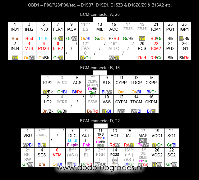
Nomenclature (other synonyms encountered between parentheses):
ACC – A/C clutch relay
ACS – A/C switch
ALTC (ACGC) – Alternator relay, not always present
ALTF (ACGF) – Alternator switch
ATD – Automatic Transmission only, shift position for 3 and 4
ATLS – Automatic Transmission only, Lockup control solenoid valve A or B
ATNP – Automatic Transmission only, shift position neutral
BKSW – Brake switch, not always present
CKP (CRNK) – Crankshaft position, Pulse or Mass, gives multiple pulses during each cam shaft rotation (20+ pulses)
CLSW – Some manual transmission models only, clutch switch
CYP (CYL) – Cylinder position, Pulse or Mass, gives 1 pulse during each cam shaft rotation
DLC (TXD/RXD) – Data link connector
ECT (TW) – Engine coolant temperature
EGRL – Exhaust gas recirculation lift sensor
EL (ELD) – Electric load detection
ES (EGR or ESOL) – Exhaust gas recirculation control solenoid
FANC – Radiator fan relay, not always present
FLR – Fuel relay, 1 is usually present, 2 is joint with 1 if present
IACV (EACV) – Idle air control valve, controls 2 wire type valve
IAT (TA) – Intake air temperature
ICM (IGP or IGPLS) – Ignition firing pulses, 1 and 2 are joined if both are present
IGP – Battery feed, active when key is turned, 1 and 2 are joined
INJ – Injector, the number refers to the cylinder number used (1 is on the side with the belts)
IP – Linear air fuel sensor function
LABEL – Linear air fuel sensor function
LG – Grounded shield, for CYP, TDC, CKP and PO2S wires, 1 and 2 are joint
MAP (PB) – Manifold absolute pressure
MIL (WARN) – Motor indication light, provides the blinking light (CEL) signal
PCS – Purge cut-off solenoid
PG – Ground circuits, 1 and 2 are joined and connected to chassis at G101 at the thermostate housing
PO2H (HTCNTL or O2SHTC) – Oxygen sensor heater control, connects to battery to activate the heater
PO2S – Oxygen sensor signal
PSW – Power steering switch
SCS – Service check connector, short to SG2 to read CEL codes
SG – Sensor circuit ground, 1 is for MAP circuit, 2 for all other sensors
SIL – Shift indicator light
SLU – Automatic transmission, inter lock control unit
STS – Starter switch
TDC – Top dead centre, Pulse or Mass, gives 4 pulses during each cam shaft rotation
TPS (TH) – Throttle position signal
VBU – Back up battery feed, always hot (unless battery is removed)
VCC – 5V sensor feed, 1 is for MAP circuit, 2 for all other sensors
VS – Linear air fuel sensor function
VSS (VSP) – Vehicle speed sensor
VTM – Oil pressure switch
VTS – VTEC solenoid, only present on VTEC equiped vehicles
Below I included the MA/MB OBD1 ECU layouts for D15Z8 and B18C4. The connectors and layout are very similar to the common OBD1 ECUs but differ in numbering. B18C4 exclusive is indicated by a single * and D15Z8 exclusive by a double **.
There are two warnings when using MA/MB chassis and wire looms;
1) the A-connector does not fit without modification and
2) the CKF circuitry is not compatible to P06/P28/P30 type ECU’s, therefore remove the CKFP and CKFM pins in that case.
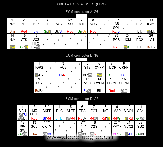
Nomenclature additions and alterations specific for MA/MB Civis:
CKF – Crankshaft speed fluctuation sensor Pulse or Mass
ECONO – Econo indicator light, D15Z8 only
IAB SOL – IAB control solenoid valve
IMOCODE – Immo system
LG – Grounded shield, slightly different compared to ‘normal’, 1 for CYPP, TDCP, CKPP, CKFP and 2 for O2S wire and DLC ground, 1 and 2 are joint at G101 at thermostate housing
Pins not mentioned here are (under an alternative name) in the OBD1 comprehensive list above in this article. The position is always the same in that case, so it should not be hard to cross reference and find it.
Please, send any questions and/or remarks to me.
Dodo Bizar
22 replies on “OBD1 Pinouts”
Hello!
First and foremost congratulations on your project. And this knowledge database is so usefull for all of us.
I actually was hoping that you or someone here could help me out… I have a 1996 1.4i Civic (MA8 with a D14A2).
Unfortunately its been sitting for over a year now because of an error i couldnt fiz so far. The car barely starts and is in limp mode.. after jumping the connector it throws a code 4 which i believe its a CKP sensor… after searching o found that the sensor is in the distributer and bought a used one. After instalation it was still doing the same soni eent and bought another and guess what, still the same. I just dont know what else to do… any advice ?
Thanks so much
Hey Bruno, indeed code 4 is CKP and I normally expect the CKP sensor in the distributor body. One question since I do not know the D14A2 that well: the distributor comes with 9 wires? 2+7 right? If not tell me.
Assuming both distributors are functioning ok and the problem lies elsewhere you practically can only check and repair the wires from the ECU to the distributor. There is literally no other reason that could cause a single code 4. (If more codes appear thats a different story, than often ground signals are not ok). Testing is pretty easy: disconnect the ECU and measure the following 2 wires in the engine loom for resistance: B15 to B16 in OBD1 counting order (these are CKPP and CKPM). If resistance is between 350-700 ohm, the wiring and distributor would seem fine, the problem is most likely in the ECU. If the resistance is not ok, repair the wire that is broken (or distributor, but we assume the problem is not there).
Thanks for your reply. The distributor is the one with two plugs yes (2+7 pins).
I will try to test as you indicated.. In case I need to replace the ecu I also need to replace the ignition and keys correct ?
Once again, thank you so much for your help..I really wanted to get this car on the road again ai I just love it.
Best regards!
Option A: (not knowing the exact details, so there is some guessing here) best option would be to have the ECU reprogrammed for your current key.
Option B: If you want to take the key and ECU from another car I believe it’s not the ignition that needs replacing, but a small box somewhere else. The ignition just holds the code reading sensor and can be freely replaced… if I remember correctly. I believe there is a box somewhere beneath the dash with the actual code (disabling starter if code not correct).
Option C: go to real OBD1 ECU like P06 and have it programmed/tuned for your engine. Will involve rewiring probably though… but ommits the key code.
Lets hope its a simple broken wire that can be replaced!
Fingers crossed ! Will get back to you as soon as I have some news !
Make sure they are spaces correctly from the magnets in the distributor. Not too far but almost touching. Make sure distributor isn’t 180 degrees out. A lot of manufacturers do it by mistake. Easy fix tho just take it apart.
Just another question if you dont mind., You mentioned ground signals.. is that something I can check easily too ?
I remember in the beggining I ha another code I believe misfire or something similar..
Ground problems are common but actually easy to fix. First there is the big G101 terminal on the termostat housing. Its bolted down with an M6 bolt. That basically connects all grounds in the wire harness together. Then there are two wires from the engine to the chassis, one on the transmission, the other on the valve cover (gets removed / lost often).
All those connections (5 M6 bolts in total) need to be clean and free of grease. When people disconnect and reconnect those (or don’t reconnect at all) without cleaning grease and using a bit of sandpaper often irratic problems occur. Many error codes all at once, irratic failures, that stuff.
This site has thought me some i have grounding issues with my car the check engine light is on but the fuel pump won’t prime if i ground the relay it works fine so i think my issue is definitely ecu grounds
Read the error codes to get a better understanding of the problem first. (Short circuit the 2 pins from the 2-pin Service Check Connector with each other, set the key on contact, CEL should be blinking error codes). That should be your first clue whats going on.
Hello, can I chip P1J ecu from D14A2 it’s OBD1 ecu. And can I put it in my turbo D14A4 and tune it
Not that I am aware. Technically you might find someone who is able to alter the mapping directly nowadays, but converting to OBD1 is solely done by me and many others in order to chip and map EJ9 cars properly. Other old-school methods are to piggy bag the ECU but I would not recommend that.
First off all, big thanks for your job !
just note that it would be fine if the pin numbering more consistent, because the numbering on these pics are different from the numbering what used in the ecu inside (also different in P28 like and d15z8) and this make some ppl confused as I see..
Thanks. Weird, I believed I already answered your question a while ago but suddenly it seems like my website reverted a bit, so to make sure here it is again:
I use Honda’s own numbering everywhere. This means that OBD1 connectors from 5th gen Civic (EG mostly) are numbered in a different order from the ‘OBD1’ connectors found in 6th gen Civics (MA/MB chassis), sorry if this confuses, but that’s on Honda, I am very strict in these.
Hi, im completely lost. I need to wire my O2 Sensor in my OBD0 to OBD1 conversion. So i need to add some wires, but whats the pin called, are these MQS pins that go in the ODB1 connector? What is the name of them? I hope you can help me.
Sorry for letting you wait. No MQS pins. Its Multilock 40/70 for OBD1 and MIC/HSG for OBD0, but unfortunately the HSG are out of stock and long gone it seems.
Hi, i got a d15b8 ecu and i connected all the wiring and my ej9 won’t start, when i turn the ignition it primes the fuel pump but the injectors aren’t firing, i cut the wiring from the injectors and put new wires that go straight to the ecu pins for the injectors, but they dont work
That’s hard to diagnose with so little info actually… did the ECU come with a immobilizer which now prevents running? Although you say fuel pump is primed… that should not be the case when immobilizer is there?
Hi, I was wondering if you have a wiring diagram for MB1 D16Y3 Civic. I recently got D16Z6 from CRX Del Sol obd1 and I can’t find any clues online on how to wire it properly. I’m trying to figure out how many differences there are between these two engines when it comes to wiring them.
Wild guess: can you check the OBD1 D15Z8 pinout? Maybe with some of the CKF stuff out… would that be a match? Really guessing here.
Beste, toffe uiteenzetting heb er veel aan doch vraagje , aanpassingen aan de A connector kan/wil je me die vertellen ?
mvg
patrick
There will be two ribs on the top side of the connector slightly moved to a different position. Removing those ribs will make it work.