
EDM/USDM/JDM (D15Z6/D16xx, B16xx, B18xx)
On this page the OBD2a scheme from a variety of OBD2a cars is presented. Some connections are different from car to car. Others are less important (read: not occurring in OBD1 cars). Both types of connections are marked grey.
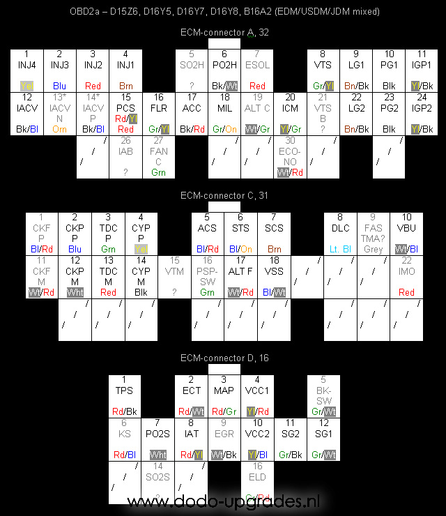
Nomenclature:
ACC – A/C relay
ACS – A/C switch
ALTC – Alternator relay, for control purposes, not present on all ECU’s
ALTF – Alternator switch
BKSW- Brake switch, for control purposes, not present on all ECU’s
CKF – Crankshaft speed, (P)ulse or (M)ass, gives 12 pulses by LED during each crank shaft rotation, not present on all ECU’s
CKP – Crankshaft position, (P)ulse or (M)ass, gives several pulses (~20?) during each cam shaft rotation
CYP – Cylinder position, (P)ulse or (M)ass, gives one pulse during each cam shaft rotation
DLC – Diagnostic connector, communication signal to the 3 wire connector next to the SCS connector
ECO – ECONOMO light, not present on all ECU’s
ECT – Engine coolant temperature
EGR – Unknown function (probably related to EGR), not present on all ECU’s
ELD – Electric load detection, not present on all ECU’s
ESOL – Unknown function (probably OBD1 EGR), not present on all ECU’s
FANC – Fan relay, for control purposes, not present on all ECU’s
FAS – Completely unknown function to me
FLR – Fuel relay
IAB – Secondary butterfly valve (B18C4)
IACV – Idle air control valve, controls the 2 wire type IACV valve or in case of N and P controls the 3 wire type IACV
IAT – Intake air temperature
ICM – Ignition pulses, 1 is always present
IGP – Battery feed, only active when key is turned
IMO. – Checks IMO code of the key and activates FLR if correct
INJ – Injector, the number refers to the cylinder used (1 is on the side with the belts)
LG – Ground for battery circuit
MAP – Manifold absolute pressure
MIL – Motor indication light, this one gives the control engine light (CEL) signal
PCS – Control solenoid, this one is for the small black cylindric valve on the back of the IM
PG – Ground for battery circuit
PO2H – Primary oxygen heater switch, not present on all ECU’s
PO2S – Primary oxygen sensor signal
PSP. – Power steering switch, not present on all ECU’s
SCS – Service connector switch, checks if the SCS connector is hot wired (for reading engine error codes)
SG – Ground for 5V circuit, 1 is for the MAP sensor, 2 is for the other sensors
SO2H – Secondary oxygen heater switch, not present on all ECU’s, position not certain
SO2S – Secondary oxygen sensor signal, not present on all ECU’s, position not certain
STS – Starter switch
TDC – Top dead centre, (P)ulse or (M)ass, gives four pulses during each cam shaft rotation
TPS – Throttle position signal
VBU – Back up battery feed, always active (unless battery is removed)
VCC – 5V feed, 1 is for the MAP sensor, 2 is for the other sensors
VSS – Vehicle speed sensor
VTM – Oil pressure switch, not present on all ECU’s
VTS – VTEC solenoid
VTSB – Secondary VTEC solenoid for 3-stage VTEC engines (D15B)
Many OBD1 ECU’s use a VTM or VTPS (VTEC Pressure Switch) to monitor if there is enough oil pressure to engage VTEC safely. A few OBD1 engines and many OBD2 engines lack this VTM sensor. Not having the physical pressure sensor, but running an ECU that does need it will throw a code 22 engine error for VTEC oil pressue. This can be omitted by splitting the VTS wire and connecting the second end to VTM or VTPS on the ECU. This will let the ECU think there is enough oil pressure. Although preferably you should remove the VTEC oil pressure check from the ECU software if there is no physical sensor. The splitting trick generally works, but has caused me in the past to throw a code 22 once while driving.
Please, send any questions and/or remarks to me.
Dodo Bizar
7 replies on “OBD2a Pinouts”
GReeting!
I have a question, i started with swap d15z6 OBD2A in Logo d13b7 OBD3b I rearranged the pins on the wires and realized that the diagram for obd2a does not have the same label for 4 pins on Ecm connector A positions 12 and 13 (IMO LMP); 19 (NEP); 25 INO CD.
Is it possible to connect it to work?
Please help!
The NEP is not a problem, it is actually similar/same/interchangeable with IGR. Until OBD2a most distributors had IGR as output. From OBD2b those are mostly removed from the distributor and replaced by a NEP on the ECU. Those signals typically go to your tacho and thats it. Worst case there is no working tacho after the swap… perhaps not electrically fully sound, but a splice from ICM may fix that.
The other pins may be a problem regarding your key code. Probably different systems going from 1 to 3? wires, not really sure about all these functions. People usually go away from OBD2 to OBD1, not interchanging. Removing the IMO part in the ECU may be your solution, but I am not sure here and don’t have the information to provide a definitive answer, sorry.
Hi i have a jdm 96 civic which I’m trying to convert to obd1 i bought a usdm M/T obd2a harness and did some changing of the layout but the ecu side got me puzzled I ordered a jumper harness and its not working 1 plug has 31 pins 1 have 25 pins and the other have 16 i tried searching for wiring diagrams online but all I’m finding is different one with different wire colors please help
I am a bit puzzled as well… can you send me pictures of the connectors per email? High resolution with all wire colors and positions as identifiable as possible. Maybe I can see what you got.
Sure i can send a pic of the connector asap
can you do a write up on the shock tower plugs for ek eg ej and del sol
Can’t promise anything… my time for this site comes and goes, but I’ll remember your request. I have been digging up those tower plugs myself from time to time so I see the usefulness indeed.