
EDM PM5/P04 (D15B2), PM7 (D16A9/D16Z5), PW0 (B16A1)
On this page I present a number of OBD0 pinouts known to me. There are small differences between the 4th gen and 5th gen Civic D15B2 engines. The first has the PM5 ECU and the latter one has the P04 ECU. The pinout is based on the P04, small differences in the PM5 are marked between brackets ( – ).
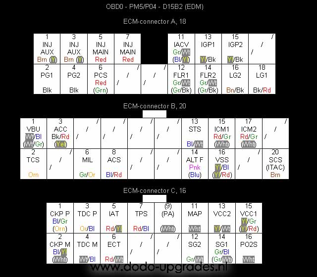
Nomenclature DPFi:
ACC – A/C relay
ACS – A/C switch
ALTF – Alternator switch
CKP – Crankshaft position, (P)ulse or (M)ass, gives several pulses (~20?) during each cam shaft rotation
ECT – Engine coolant temperature
FLR – Fuel relay
IACV – Idle air control valve, controls the 2 wire type IACV valve
IAT – Intake air temperature
ICM – Ignition pulses
IGP – Battery feed, only active when key is turned
INJ – Injector, AUX for auxilry and MAIN for MAIN injectors, the wires go from 4 to 2 about 30 cm from the ECU
ITAC – Ignition timing connector, same timing functionality as SCS, but no error code reading (read from LED instead)
LG – Ground for battery circuit
MAP – Manifold absolute pressure
MIL – Motor indication light, this one gives the control engine light (CEL) signal
PA – Atmosferic pressure
PCS – Control solenoid, this one is for the small black cylindric valve on the back of the IM
PG – Ground for battery circuit
PO2S – Primary oxygen sensor signal
SCS – Service connector switch, checks if the SCS connector is hot wired (for reading engine error codes)
SG – Ground for 5V circuit, 1 is for the MAP sensor, 2 is for the other sensors
STS – Starter switch
TCS – Tandem valve control solenoid
TDC – Top dead centre, (P)ulse or (M)ass, gives four pulses during each cam shaft rotation
TPS – Throttle position signal
VBU – Back up battery feed, always active (unless battery is removed)
VCC – 5V feed, 1 is for the MAP sensor, 2 is for the other sensors
VSS – Vehicle speed sensor
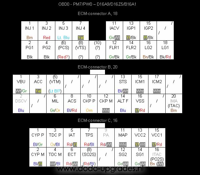
Nomenclature changes for MPFi:
CKP – Same as for DPFi, however located at a different location
CYP – Cylinder position, (P)ulse or (M)ass, gives one pulse during each cam shaft rotation
DSCV- Unknown (probably solenoid located near IM), found on D16A9 and D16Z5
IMA – Idle mixture adjustment, found on D16A9, the D16Z5 has ITAC instead
INJ – Injector, the number refers to the cylinder used (1 is on the side with the belts)
SO2S – Secondary oxygen sensor signal on B16A1
VTM – Oil pressure switch, only present on B16A1
VTS – VTEC solenoid, only present on B16A1
A10 connects to a solenoid on B16A1 engines. The function and location of this solenoid are unknown to me. I never had problems leaving this wire unconnected in OBD1 conversions. Beware of mixing up 5th gen DPFi CKP and MPFi CYP wires. They have the same colors, though different functionalities!
D16Z5
About the D16Z5 engines I have some doubts. I do not know for instance if they have the DSCV and PA connections. Pins B20 and C16 need some clarification. In basic the cars without a catalyc converter (D16A9 in this case) have ITAC on C16 and use IMA (it is just a screw on a potentiometer) on B20 for the correct mixture. Cars with catalyc converters (D16Z5 and B16A1 in this case) have ITAC on B20 and use the lambda sensor to monitor the idle mixture.
Any questions and/or remarks send them to me.
Dodo Bizar
7 replies on “OBD0 Pinouts”
Hi, noticed you mixed up PM6 and PM7 between title and article… Which one is good? ?
Wow thanks man for finding this error! Its all PM7, that was an age old typo. Changed it.
I have a question. I have a first gen jdm b16a in a 99 ex coupe. Now the motor is setup to run obd1. Dizzy + adapter harness chipped p28 with adapter harness. The chip tune is for the setup as it sits. Now my question is how do i get the crank position sensor code off so the ecu wont keep the motor in limp mode? Any help will be great. Note. The car does run but like absolute shit. Do i need to take whole car to get tuned fully cause it only on hamotorsports base tune and the ecu if from ha as well. Or is there anything else that needs to be done or what have you?
I also have obd1 ev1 injectors. And when i jump the service connector the 2 codes i keep getting is 4 and 7 4 crank position sensor 7 throttle sensor. And so im stuck. Please help lol.
Code 4 might be very easy… the number of teeth on an OBD0 dizzy crank sensor is not the same as with OBD1/2, therefore it errors is my guess. Unless you actually mean the dizzy is already an OBD1/2 type, than I am lost.
If your current dizzy is the original OBD0 dizzy, swap it to an OBD1/2 variant (not just do the wiring, the physical dizzy needs to be swapped).
Code 7 is indeed TPS, that one cannot be hard to figure out. Did you perhaps swap TPS with MAP sensor? Happens often. And check the wire order on TPS if its ok. Grab a workshop manual from somewhere on the internet and you should be able to figure it out, code 7 cannot be difficult.
Hi out of curiosity, I wonder if you guys could help. I have a d16a9 that I’m installing an after market management on. It only takes two cables for signal from the dizzy, would I use the TDC or the crank prosion sensor. And can I connect the power direct to the coil and bypass the icm
Hey, I guess for a part you need to consult the manual of the after market system. CYP / TDC / CKP give either 1 / 4 / 16? pulses per camshaft revolution. All those are VR sensors. Usually aftermarket systems have a hard time coping with those. I have seen aftermarket systems bringing there own Hall effect sensor and getting a teeth plate on near the crank pulley. Actually once I saw a crank pulley being cut down into a teeth pattern (the Jamex Turbo Civic had this using DTA system). I have seen direct connection to after market coil packs, but not to sure what are does and don’ts there. Check the documentation.