
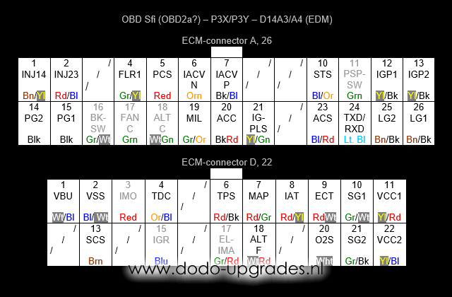
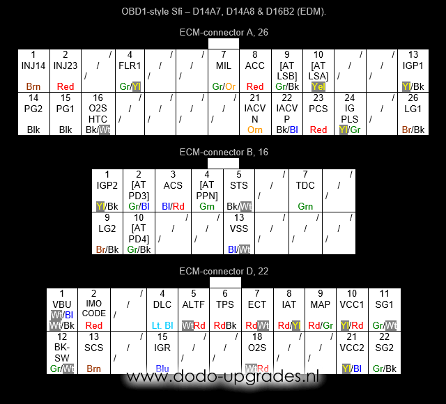
Two connector type EDM P3X (D14A3) and P3Y (D14A4) and OBD1 three connetor type D14A7, D14A8 and D16B2
On this page the OBD pinouts sheme of some Sfi ECUs are presented. Sfi stands for simplified fuel injection. The first pinout is from the in Europe well known EJ9 chassis type with 1.4 engine. The MA/MB type chassis also were delivered with a similar Sfi ECU, but using the classic OBD1 type connectors. That pinout is posted on the bottom of this page. In function both pinouts are very similar, but in layout the P3X and P3Y from EJ9 are very different from the MA/MB chassis types.
In both cases these pinouts can be used to convert to classic OBD1. My article on OBD1 swapping in an EJ9 should help you along, even for MA/MB chassis types.
Some connections are different from car to car. Those are marked grey. These pinouts are very alike pinouts that used for certain D16 engines in Australia and certain D15 engines in the Middle East. The exact specs of these engines are unknown to me. However, these pinouts may be helpful for more people.
Note that all connectors are the same as the A and D (and B) connectors from the OBD1 ECU’s. However, the numbering has changed to OBD2a style.
Nomenclature (alternate naming):
ACC – A/C clutch relay
ACS – A/C switch
ALTC – Alternator relay, not always present
ALTF – Alternator switch
BKSW – Brake switch, not always present
ECT – Engine coolant temperature
ELIMA – Electric load detection, not always present
FANC – Radiatior fan relay, not always present
FLR – Fuel relay circuit
IACV – Idle air control valve, controls 3 wire type valve, Negative and Positive
IAT – Intake air temperature
IGPLS – Ignition pulse
IGP – Battery feed, active when key is turned, 1 and 2 are joined
IGR – Ignition pulse return signal
IMO (IMOCODE) – Immo system
INJ – Injector, the numbers refer to the pair of cylinders connected (1 is on the side with the belts)
LG – Grounded shield, 1 for O2S wire and ground for distributor, 1 and 2 are joined
MAP – Manifold absolute pressure
MIL – Motor indication light, provides the blinking light (CEL) signal
O2S – Oxygen sensor (lambda sensor) signal
PCS – Purge cut-off solenoid
PG – Ground circuits, 1 and 2 are joined and connected to chassis at G101 at the thermostate housing
PSPSW – Power steering switch, not always present
SCS – Service check connector, short to ground to read CEL codes
SG – Sensor circuit ground, 1 is for MAP circuit, 2 for all other sensors
STS – Starter switch
TDC – Top dead centre LED sensor, gives 4 pulses during each cam shaft rotation
TPS – Throttle position signal
TXD/RXD (DLC) – Data link connector
VBU – Back up battery feed, always hot (unless battery is removed)
VCC – 5V sensor feed, 1 is for MAP circuit, 2 for all other sensors
VSS – Vehicle speed sensor
Nomenclature additions and alterations specific for MA/MB Civis:
ATPD – Automatic Transmission only, shift position for 3 and 4
ATLS – Automatic Transmission only, Lockup control solenoid valve A or B
ATPPN – Automatic Transmission only, shift position neutral
DLC – See TXD/RXD above
IMOCODE – See IMO above
O2SHTC – Oxygen sensor heater control, connects to IGP to activate the heater
Please, send any questions and/or remarks to me.
Dodo Bizar